petSD+ rev. 1 Errata
last edit 2015-06-28
18.432 MHz crystal required
Originally, it was intended to operate the petSD+ at 8 MHz
by the internal RC oscillator. As it turned out, this setting is
too slow for a reliable operation. As a consequence, the 18.432 MHz
crystal X1 and the capacitors C7, C8 (18 pF) are required.
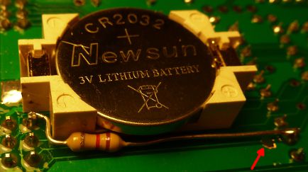
The crystal does not fit under the socket, so it has to move on the
bottom side of the PCB.
Issues in schematics (and thus in the PCB also)
The MISO output of buffer IC4 pin 12 drives against MISO from the
ISP connector P4 during ISP programming.
If you do not use ISP programming, no further steps are required.
Otherwise, cut the trace from IC 4 pin 12 and connect IC 4 pin 12
via a resistor of 680 ohms to the ISP connector P4, pin 1.
PCB issues
- footprint of CV1 too small
- optional crystal X1 may not fit under a socket
- some connections of the SD slot (card detect, write protect, common)
are difficult to solder because of the size of the pads
If you find anything else, please drop a line to
nils.eilers@gmx.de.